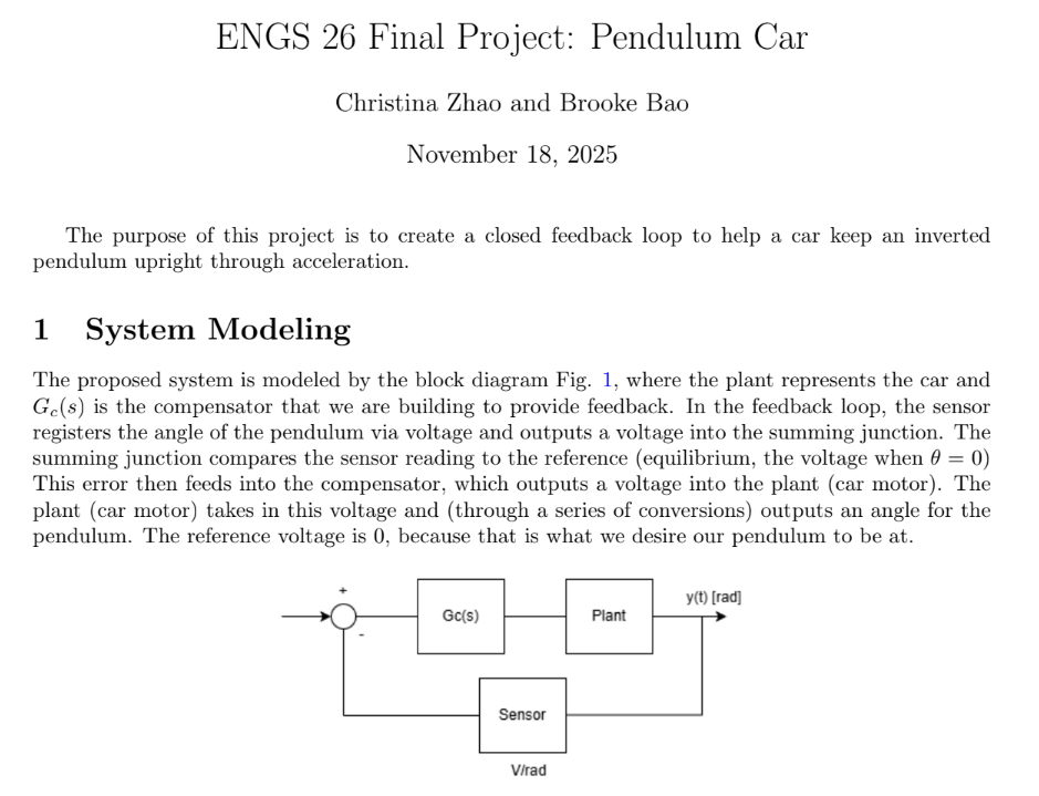
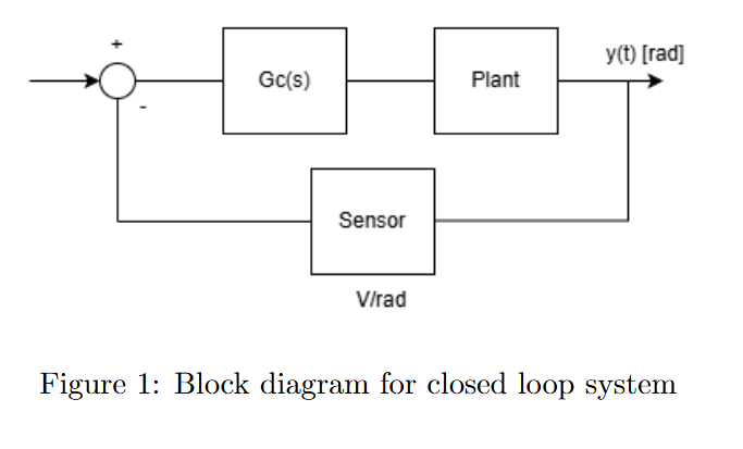
The system was modeled as a feedback loop consisting of a compensator, motor, drivetrain, cart-pendulum dynamics, and angular position sensor. Equations of motion for the cart-pendulum system were derived from Newtonian mechanics and linearized about the upright equilibrium.
These equations were transformed into the Laplace domain to obtain the plant transfer function relating motor voltage input to pendulum angle output.
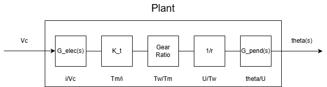
Measurements were taken to estimate the transfer function for each block, except the compensator which we must design. This includes the following (see report for more details):
A PID controller was selected due to its ability to balance responsiveness, stability, and steady-state accuracy.
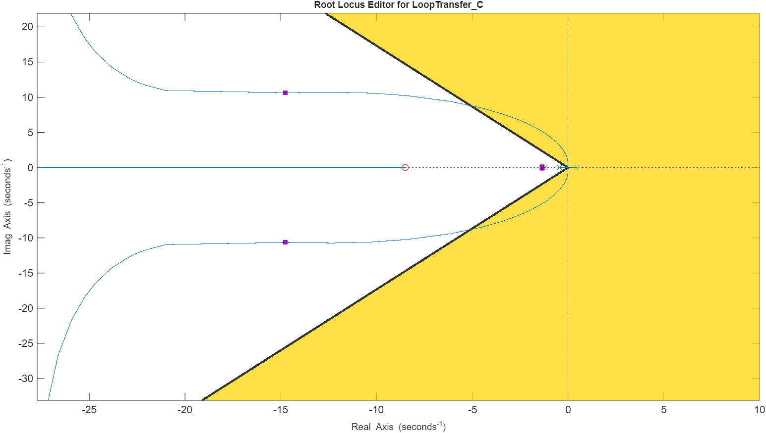
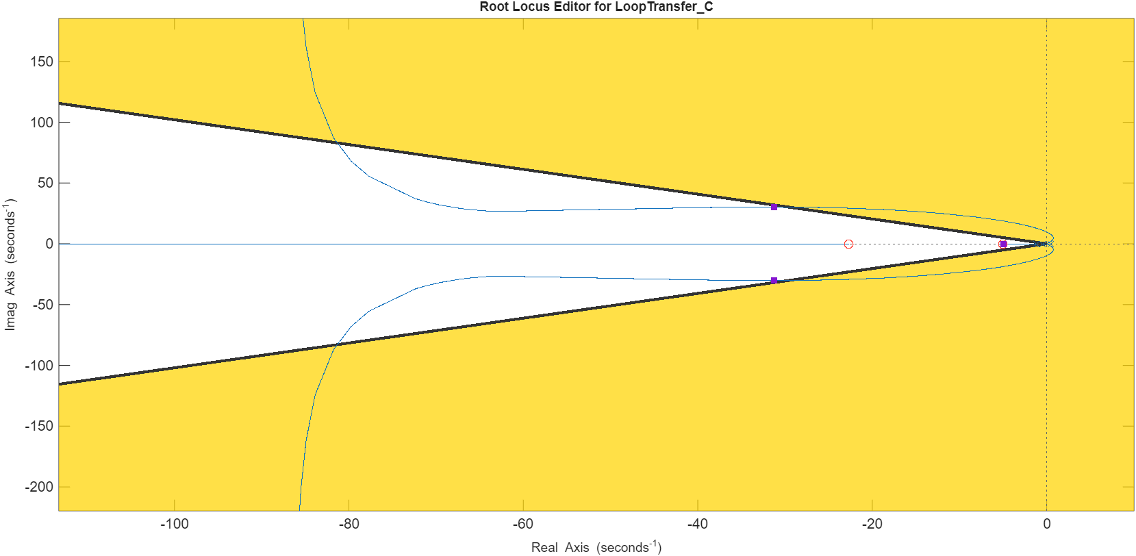
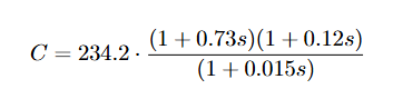
An ideal compensator was first designed in MATLAB using SISOTOOL and validated through root locus, Bode, and Nyquist analyses. The transfer function was derived from the graph, and component values were solved for and translated into a physical analog circuit using resistors and capacitors.
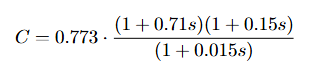
Challenge: the first compensator (we called "theoretical") derived had a slow performnace, response rate, and had a large gain that saturated the power amp of the motor--there were clearly factors like friction and other dynamics we did not model for. Resistor and capacitor values were adjusted one by one to address each issue. More detailed problems and tuning can be found in the report below.
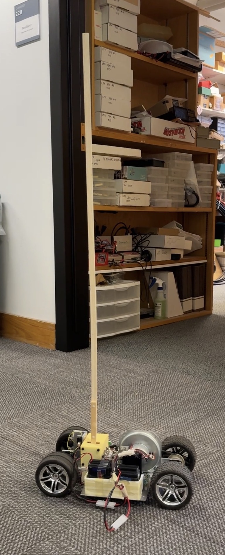
The final controller successfully stabilized the inverted pendulum in hardware. The system demonstrated fast response, minimal overshoot, and robust recovery from disturbances.
Frequency-domain analysis confirmed adequate phase margin and closed-loop bandwidth, while time-domain testing validated real-world performance.